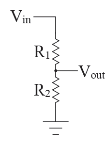
A voltage divider (also known as a potential divider) is a simple circuit which turns a large voltage into a
smaller one. Using just two series resistors and an input voltage, we
can create an output voltage that is a fraction of the input.
 The supply voltage (Vin) is divided between the two resistances (R1 and R2 ) to give an output
voltage Vout which is the voltage across R2.
Voltage dividers are one of the most fundamental circuits in electronics.

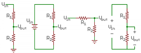
Examples of voltage divider schematics. Shorthand, longhand, resistors at same/different angles, etc.
We’ll call the resistor closest to the input voltage (Vin) R1, and the resistor closest to ground R2. The voltage drop across R2 is called Vout, that’s the divided voltage our circuit exists to make.
That’s all there is to the circuit! Vout is our divided voltage. That’s what’ll end up being a fraction of the input voltage.
The Equation
The voltage divider equation assumes that you know three values of the above circuit: the input voltage (Vin), and both resistor values (R1 and R2). Given those values, we can use this equation to find the output voltage (Vout):

This equation states that the output voltage is directly proportional to the input voltage and the ratio of R1 and R2.
Simplifications
There are a few generalizations that are good to keep in mind when using voltage dividers. These are simplifications that make evaluating a voltage dividing circuit just a little easier.First, if R2 and R1 are equal then the output voltage is half that of the input. This is true regardless of the resistors' values.
If R2 is much larger (at least an order of magnitude) than R1, then the output voltage will be very close to the input. There will be very little voltage across R1.
Conversely, if R2 is much smaller than R1, the output voltage will be tiny compared to the input. Most of the input voltage will be across R1.


Tidak ada komentar:
Posting Komentar